Boiler Feed Pump Calculation: Complete Engineering Sizing Guide, Formulas & Feed Tank Sizing
Performing an accurate boiler feed pump calculation is the foundation of reliable steam plant design. This comprehensive technical guide details the governing fluid mechanics equations, step-by-step sizing formulas, Total Dynamic Head (TDH) calculations, boiler feed tank sizing parameters, and cavitation risk mitigation using our interactive feed pump rate calculator.
Need Immediate Calculations for Your Steam Plant?
Skip manual paper calculations. Use our web-based tool with built-in IAPWS-IF97 fluid property engines, Darcy-Weisbach friction modeling, and instant PDF report export.
1Overview of Boiler Feed Pumps in Industrial Steam Systems
In steam generation plant design and thermodynamic Rankine cycles, the boiler feed pump (BFP) acts as the heart of the fluid loop. Operating downstream of the deaerator or hotwell feed tank, its sole purpose is to inject high-pressure feedwater into the boiler drum or steam generator coils to match the evaporation rate.
Because steam boilers operate under high pressure (often from 10 bar up to 150+ bar in industrial power generation), the feedwater pump must overcome not only the boiler internal drum pressure, but also static elevation differences, economizer pressure drops, control valve head losses, and line friction. Performing a rigorous boiler feed pump calculation prevents costly operational failures such as thermal shock, drum water level depletion, electric motor trips, and catastrophic impeller erosion due to cavitation.
Delivers water at pressures higher than boiler safety valve settings.
Handles hot feedwater (105°C to 180°C) near saturation vapor pressure.
Must maintain stable drum water levels across severe firing rate fluctuations.
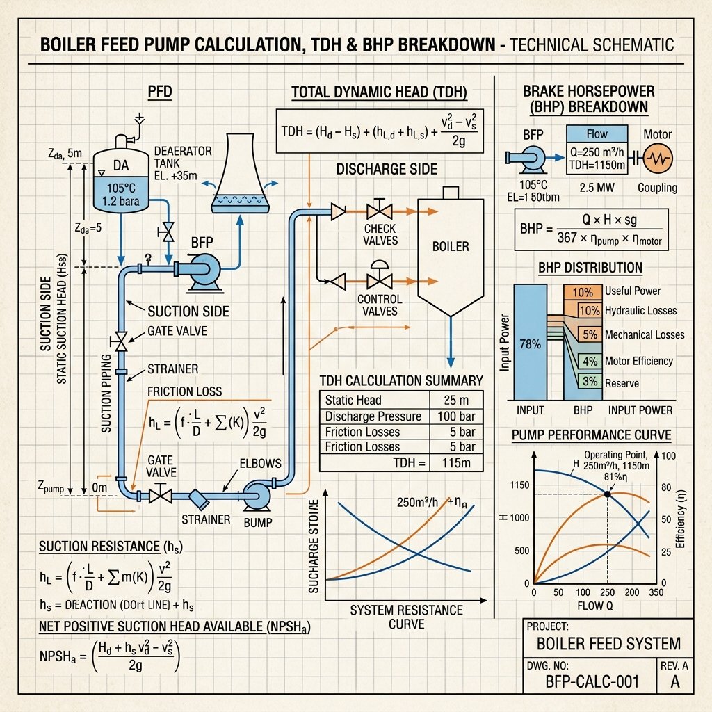
Figure 2: Thermodynamic & Hydraulic Schematic for Boiler Feed Pump Sizing (TDH, NPSHa, Suction Lift, and Motor BHP Breakdown).
2Boiler Feed Pump Calculation Formula & Required Flow Rate
The primary step in any boiler feed pump calculation formula workflow is determining the required volumetric flow rate (Q_design). The feed pump rate must satisfy the boiler maximum continuous rating (MCR) steam production, account for continuous or batch blowdown water losses, and incorporate an industry-standard safety capacity margin.
Step 1: Mass Flow Rate & Blowdown Balance
Boiler blowdown is essential to remove dissolved solids (TDS) and prevent scale buildup inside the boiler tubes. The total required feedwater mass flow rate (M_feedwater) is given by:
- M_steam: Boiler nominal steam capacity (kg/h or lb/h).
- X_blowdown: Blowdown fraction (e.g., 0.05 for 5% blowdown).
Step 2: Operating Volumetric Flow Rate (Q_operating)
Water density drops significantly at high temperatures. Using the IAPWS-IF97 thermodynamic standard , density (ρ) is computed at the feedwater temperature (e.g., ρ = 954.7 kg/m³ at 105°C). The operating flow rate is:
Step 3: Rated Pump Design Flow Rate (Q_design)
Under industrial standards (ASME BPVC Section I and Hydraulic Institute HI 1.3 ), boiler feed pumps must be oversized by 15% to 20% to rapidly restore drum level during sudden steam load surges:
3Total Dynamic Head (TDH) & Piping Friction Losses
Total Dynamic Head (TDH) represents the net specific hydraulic work per unit weight required from the pump to lift and press water into the boiler steam drum. Expressed in meters of liquid column (m) or feet (ft), TDH is defined as:
A. Discharge Head Component (H_discharge)
- P_boiler × Margin: Boiler drum pressure with a 3% to 5% overpressure safety margin to overcome safety valve settings.
- ΔP_economizer: Pressure drop across the economizer tubes and feedwater heaters.
- ΔP_valves: Pressure drop across feedwater control valves, non-return check valves, and isolation gate valves.
- ΔP_pipe_friction: Calculated via Darcy-Weisbach equation: h_f = f · (L/D) · (v² / 2g).
- Z_discharge: Static elevation of the boiler drum inlet relative to pump centerline.
B. Suction Head Component (H_suction)
Since the suction tank (deaerator) is placed elevated above the pump floor, Z_suction provides a positive static head boost.
4Pump Power, Shaft Power & Motor Horsepower (BHP)
Calculating power requirements ensures proper electric motor driver selection without risk of thermal overload during high-load conditions. Power is computed across three stages:
Clean fluid energy delivered to the water stream:
Shaft power input required, accounting for pump hydraulic efficiency (η_pump):
Includes standard motor service factor margin (10% to 15%):
5Boiler Feed Tank Sizing & Deaerator Retention Rules
Proper boiler feed tank sizing (also referred to as deaerator storage tank sizing) is just as critical as pump selection. The feed tank stores preheated, deaerated water to absorb condensate returns and makeup water demand.
Standard Retention Time Rule (10 to 20 Minutes)
According to industrial boiler guidelines (such as Spirax Sarco Steam Engineering Standards ), a boiler feed tank must hold an effective working volume corresponding to 10 to 20 minutes of maximum boiler capacity (MCR).
Since the feed tank should only operate between 20% minimum level and 80% maximum level (leaving 20% vapor/surge space), Total Tank Volume = V_effective / 0.60.
Deaerators operate at saturated temperature (105°C at 0.2 bar g). To prevent feed pump cavitation, the tank centerline must be elevated 5 to 9 meters above the pump centerline.
6Using a Feed Pump Rate Calculator & Feeding Pump Rate Calculator
When engineers search for a feed pump rate calculator or feeding pump rate calculator, they require quick conversion between boiler output units (such as Boiler Horsepower BHP, Ton/hr, or kg/h) and volumetric pumping rates in GPM (Gallons Per Minute) or m³/hr.
Common Boiler Capacity Conversion Factors
| Boiler Unit | Equivalent Steam Mass Flow | Typical Pump Flow Rate (incl. Blowdown + Margin) |
|---|---|---|
| 1 Boiler HP (BHP) | 34.5 lb/hr (15.65 kg/h) at 212°F | 0.07 to 0.08 GPM (0.016 to 0.018 m³/h) |
| 1 Ton/hr Steam (1,000 kg/h) | 2,204.6 lb/hr | 1.25 to 1.35 m³/h (5.5 to 6.0 GPM) |
| 100 BHP Industrial Boiler | 3,450 lb/hr (1,565 kg/h) | 7.5 to 8.0 GPM (1.7 to 1.8 m³/h) |
7Worked Engineering Sizing Examples
Worked Example 1: 10 Ton/hr Industrial Package Boiler (SI Units)
Design Inputs:
- Steam Production Capacity: 10,000 kg/h
- Boiler Operating Pressure: 10.0 bar g (11.013 bar abs)
- Feedwater Temperature: 105°C (ρ = 954.7 kg/m³, P_vapor = 1.208 bar abs)
- Continuous Blowdown Rate: 5% (0.05)
- Flow Safety Margin: 1.15 (15%)
- Static Lift (Z_discharge): 4.0 m; Suction Static Head (Z_suction): 6.0 m
- Discharge Piping Friction + Valve Losses: 1.5 bar (150,000 Pa)
- Pump Efficiency (η_pump): 72% (0.72)
Calculation Steps:
- M_feedwater = 10,000 × (1 + 0.05) = 10,500 kg/h
- Q_operating = 10,500 / 954.7 = 10.998 m³/h
- Q_design = 10.998 × 1.15 = 12.65 m³/h (Rated Flow)
- P_discharge = (10.0 × 1.05) + 1.5 = 12.0 bar g = 1,200,000 Pa
- H_discharge = [1,200,000 / (954.7 × 9.81)] + 4.0 = 128.14 + 4.0 = 132.14 m
- H_suction = [120,800 / (954.7 × 9.81)] + 6.0 - 0.5 = 12.90 + 5.5 = 18.40 m
- TDH = 132.14 - 18.40 = 113.74 m
- P_hyd = (12.65 × 954.7 × 9.81 × 113.74) / 3,600,000 = 3.74 kW
- P_brake = 3.74 / 0.72 = 5.20 kW (7.0 HP)
- P_motor = 5.20 × 1.15 = 5.98 kW (Standard 7.5 kW Motor Selected)
8Cavitation & Net Positive Suction Head (NPSHa vs NPSHr)
Cavitation is the single most destructive risk in boiler feed pump operation. When hot feedwater experiences localized pressure drops below its saturation vapor pressure (P_vapor) inside the pump impeller eye, vapor bubbles form and violently collapse, tearing metal off impeller blades.
NPSH Available (NPSHa) Formula
Because deaerators store water at saturation equilibrium where P_deaerator ≈ P_vapor, the pressure term drops to nearly zero! Thus, NPSHa relies almost entirely on static suction head (Z_suction) minus friction losses.
9Compliance with International Engineering Standards
Our calculations and interactive software follow well-established global engineering standards:
Rules for construction of power boilers, overpressure margins, and feed piping safety.
Centrifugal pumps for petroleum, petrochemical, and heavy industrial plant services.
Hydraulic performance acceptance tests for rotodynamic pumps (Grade 1, 2, and 3).
International formulation for thermodynamic water and steam properties.
Frequently Asked Questions (FAQ)
Q1: How do you calculate boiler feed pump flow capacity?
Feed pump capacity is calculated by converting boiler steam production mass to volumetric flow at operating temperature, adding blowdown rate (typically 3% to 5%), and applying a 15% to 20% safety margin for drum level restoration.
Q2: What is the ideal elevation for a boiler feed tank or deaerator?
Deaerators are typically installed 5 to 9 meters (16 to 30 feet) above the boiler feed pump suction nozzle to ensure sufficient static suction head (NPSHa) to prevent boiling and cavitation inside the pump.
Q3: Why shouldn't I assume water density is 1000 kg/m³?
At typical boiler feedwater temperatures of 105°C to 150°C, water expands and its density drops to 954 kg/m³ or lower. Assuming 1000 kg/m³ causes a 5% to 10% underestimation of volumetric flow rate and power requirements.
Perform Your Boiler Feed Pump Sizing Now
Access our free, interactive, professional-grade feed pump rate calculator with 3D system visualization, unit toggling, and complete equation breakdowns.